SV Pilgrim - 1979 Morgan 382 - Homeport: Beaufort, NC

Thursday, May 28, 2015

Steady Progress in the Cockpit Locker

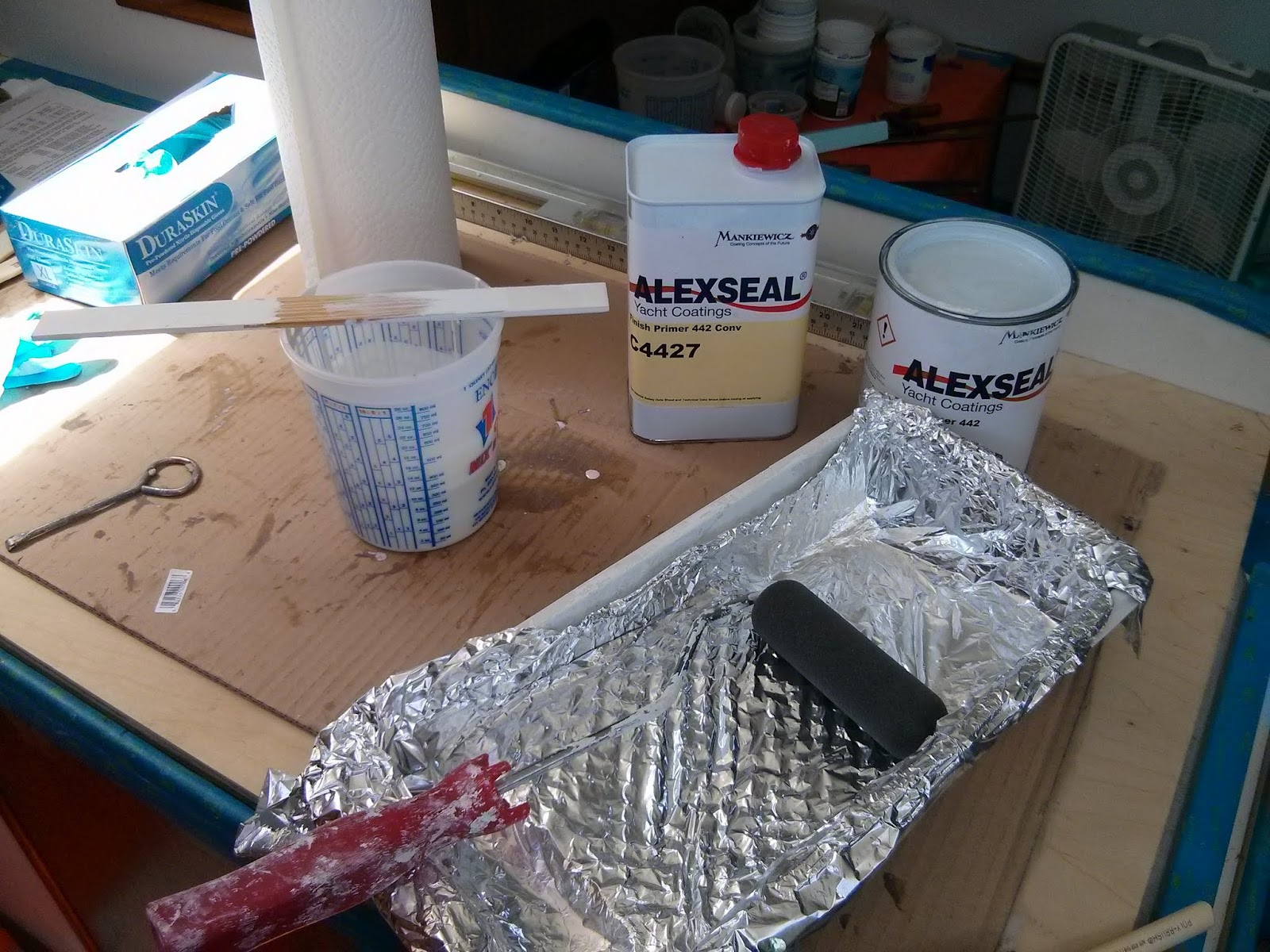
We are continuing to fabricate and install new panels and floor in the cockpit locker.  Oh yes we have also done a bit of painting…

Peering down upon fresh paint in the cockpit locker

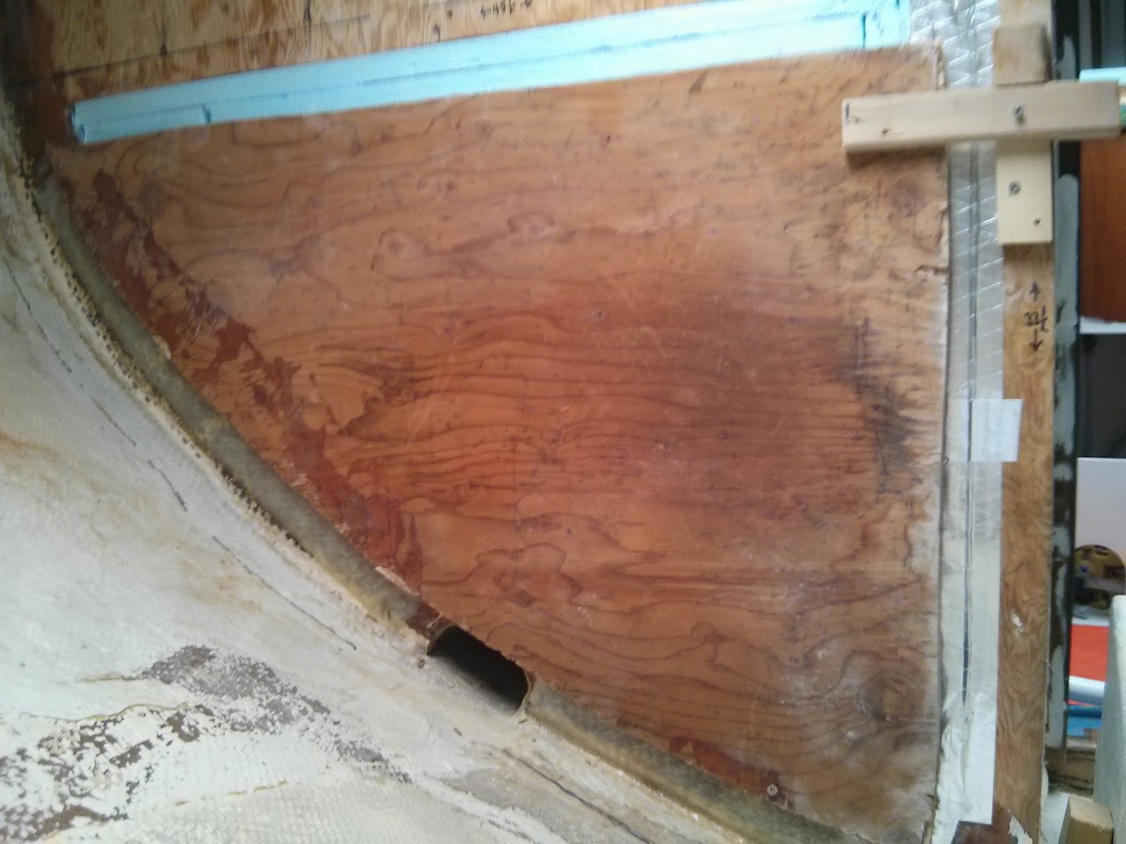
We painted the lower portion of the locker so that we could install the new floor.  Having a horizontal floor makes working in the tight space much more comfortable.

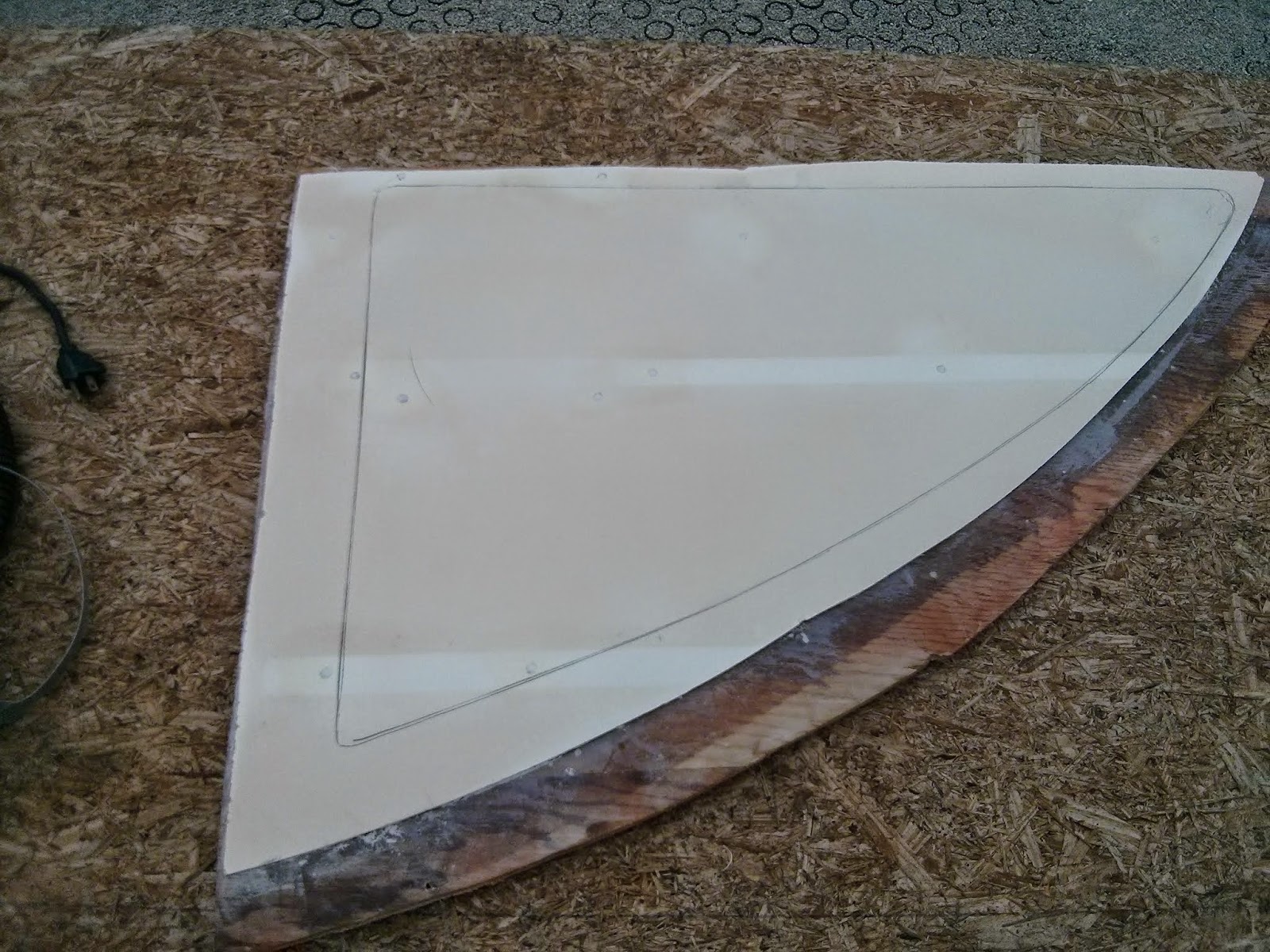
We created a template for the floor then transferred the shape to the 1/2” marine plywood used for other panels in the cockpit locker.  After a test fit and few minor adjustments, we installed an access panel in the central section of the floor.

Creating a simple access panel in the cockpit locker floor.

We sealed the underside of the flooring with a couple coats of epoxy.

The underside of the cockpit floor is with two coats of epoxy to prevent water damage.

And painted the top side.

The new locker floor viewed from the cockpit.  The cut outs at the upper left are for bilge pump drain hoses.

The ½” marine plywood is nearly exhausted.  The remaining cockpit locker panels & cabinetry are less structural and will be installed higher above the waterline.  To complete the locker refit we purchased a 4’ X 8’ sheet of ½” thick pre-finished birch plywood.  The pre-finished plywood is a bit more expensive, but we will save time and materials in the painting stage of the project.

The first of the birch  panels to go in, vertical panel along the upper aft wall, required some creative clamping. 

Employing creative clamping to hold the aft vertical panel in place while the tabbing cures.

The cockpit side walls in this area are relatively thin, 3/8”, solid fiberglass.  Using 1708 cloth to tab in a ½” plywood panel will provide a surface to which we can mechanically fasten hose clamps, hooks, or any number of locker organizers without the need to put a hole in the fiberglass wall.

Upper panel and lower brace tabbed in place. Installed stainless steel "ring" nuts on the three thru-bolts along the longitudinal side wall.

Next step will be to install a shelf along the hull and replace the tired deck scupper drain hose.

Adding a shelf, re-plumbing the deck scupper, and painting in the upper portion of the cockpit locker are next up on our to do list.


More images and notes from this on-going project are available in the Cockpit Locker Refit Photo Album

Monday, May 25, 2015

Cockpit Locker Refit

Yes we continue to make progress on the ice box. The aft panel perimeter is on its third and hopefully final round of fairing.

Much more exciting changes are happening in the cockpit locker.  We just created a new photo album devoted to the project – Cockpit Locker Refit.  We will continue to add new photos to the album as the project continues.

When we took possession of Pilgrim the vertical panel dividing the engine compartment and the cockpit locker was held in place by four bolts at the top and wood screws into the locker floor at the bottom.  The locker floor tabbing had failed due to poor construction techniques at the factory (the tabbing was bonded to gel coat on the hull interior.)  Thus the entire assembly, hanging off the bolts atop, was able to swing a couple inches into the engine compartment.

Once the tabbing cured on the new forward bulkhead we began work on fabricating a new panel to divide the engine compartment and the cockpit locker.

The effort began by using some scrap 1” X 2” to experiment with the placement and size of the panel.

Experimenting with the size and position of the panel.

Once satisfied with the concept we marked out the location of the panel along the hull.

The desired location marked on the hull and divided into two inch segments.

Dropping and measuring a plumb line from the panel above at two inch increments gave us the data we needed to transfer the curve of the hull to the new plywood divider.

Transferring measurements taken inside the boat to the 1/2" plywood. 

The effort produced a good fit.

Test fitting the new panel... we are pleased with the results.

Next we cut a large opening in the center of the panel.  This opening will provide engine access via to removable hatches.

Clamping the hatch frames in place.

After creating a frame to hold the hatches in place we tabbed the new panel in place along the hull.

Tabbing, directly to bare fiberglass, on both sides of the new panel anchor it to the hull.

And to the vertical side wall of the cockpit at the top.

Single layer of tabbing and three thru bolts secures the top of the new panel. 

We installed new bolts in three of the four original holes across the top.  This made the installation easier and adds an additional measure of structural integrity to the assembly.

With the vertical panel in place we are able to begin laying out the new cockpit floor and other pieces of new cockpit locker cabinetry.

Test fit of locker floor and template for small partial bulkhead aft.


More images and notes from this on-going project are available in the Cockpit Locker Refit Photo Album.

Thursday, May 21, 2015

New Bulkhead In the Cockpit Locker

 The template of the cockpit locker hull I created a few months ago (here is a link - January 18, 2015) has proven very helpful.  I utilized it for shaping the ice box insulation and the new plywood bulkhead.

Attaching scrap 1" X 2" to template  to attain the proper fit for the new  bulkhead.

After building out the insulation, the template fit more accurately along the hull than along the top or vertical side.  I clamped and screwed pieces of scrap 1” X 2” lumber to the plywood template to accurately capture the outside dimensions of the new bulkhead.

Tracing the template onto the sheet of marine plywood.

Once satisfied with the fit, I clamped the template atop the plywood and marked out the new bulkhead.

I am amazed at what boat owners and contractors will leave behind or toss in boat yard dumpsters. We have used a lot of recycled and reclaimed materials in our refit, but, mission critical components (thru-hull fittings, standing rigging, backing plates, etc.)  require total confidence in the materials.  New, marine plywood for bulkheads definitely falls onto our required materials list.

Some projects require absolute confidence in the materials.

We anticipate one 4’ X 8’ sheet will allow us to complete all the new structural components of the cockpit locker cabinetry.   We will be posting more information on the changes to the cockpit locker in the near future.

Installing new bulkhead.

The new bulkhead fit precisely on the initial cut.  The top and side panels, from the same sheet of marine plywood were quick to follow.

Looking down thru cockpit locker access at new bulkhead assembly. 

Initially, I installed the three pieces with fillets of epoxy and #8 X 1” countersunk wood screws.  Once the epoxy fillets cured, I cut and test fit 1708 cloth tabbing.

Test fitting layers of 1708 cloth tabbing.

Wetting out and installing large sections of tabbing in cramped quarters is definitely a two person job. Anne joined in the fun.

Anne preparing to lay up tabbing on new bulkhead.

Structurally the bulkhead is now complete.

Two to three layers of tabbing on new bulkhead.

We got big plans for the rest of the cockpit locker.  Oh yeah and an ice box to finish up.


More images and notes from this on-going project are available in the Ice Box Rebuild Photo Album

Tuesday, May 12, 2015

Molding A Semi-Circular Fiberglass Conduit

When constructing the 25" long conduit running under the ice box ( see – January 17th Post) I used prefabricated, 1” thick foam core paneling.  The paneling provided additional insulation under the box and the completed assembly added structurally to the hull by serving as a stringer between two transverse bulkheads.

The 5” long section of conduit running between the aft panel of the ice box and the new cockpit locker bulkhead does not need to provide additional insulation nor contribute structurally.  It’s sole function is to provide a water tight passage way under the ice box insulation.  Thus I chose a quicker and less costly method for building a conduit… 

Save for some two-part epoxy all the components of the conduit fabrication are pictured

Using a plastic, 1G jug and some duct tape I created a fiberglass mold for the section of conduit required.

The duct tape serves as a mold release agent and as part of the mold.

I began by cutting the  jug in half.  To assist in maintaining the shape of the plastic ran one strip of tape across the open face of the jug.  I then placed the jug on a board covered with plastic sheeting and covered it with duct tape.  Epoxy will not bond to duct tape so it serves in place of mold release wax.  The duct tape also allowed me to create a nice radius at the intersection of the jug and the base.

Test fitting the 1708 cloth on the mold.

I then cut a section of 1708 cloth to cover the mold.  One layer of cloth was adequate for my application, but additional layers could be added to create a load bearing conduit.

Time to walk away and let the epoxy cure.

I then wet out the cloth and laid it over the mold and went home for the night.

Conduit fresh off the mold.

The next morning I lifted the conduit off the mold.   While wearing leather gloves I dressed the sharp, jagged edges by hand sanding with 35 grit paper then sanded the entire piece with 80 grit sandpaper.

fitting the conduit to the hull and bulkhead.

I fit the piece in position and marked the excess material.  The single layer of cloth cut easily with a jig saw with a metal cutting blade.  I believe that tin snips would also work for shaping the piece.  Fine tuning the fit was done using 80 grit paper on an orbital sander.

Conduit bonded to hull and bulkhead with thickened epoxy and cloth tabbing.

Once satisfied with the fit, I used two small sections of fiberglass cloth to tab the base flanges to the hull.  I sealed the fore and aft ends of the conduit to the adjacent bulkheads with a fillet of thickened epoxy.  

Now it is time to bury the conduit under layers of ice box insulation.


More images and notes from this on-going project are available in the Ice Box Rebuild Photo Album

Monday, May 11, 2015

Building Out The Back of the Ice Box

Installing the final interior panel of the ice box and building out the cockpit locker components seems to be progressing at a meteoric pace relative the fairing, priming, and painting of the last few weeks.

Tabbing and fairing the aft panel into the box is going to get messy.  In preparation I masked all the freshly painted areas of the box.

Not taking any chances with the masking on the the counter tops or freshly painted ice box.
I sanded the fresh primer &  paint off the areas that will receive tabbing.
Tabbing the aft panel will require me to hang my head, arms, and a good portion of my torso into the box while handling wet fiberglass cloth.  Adding an extra set of hands to pass me materials will limit the scope of the mess.  So that portion of the project is on hold until Anne can join me for a project day on the boat.

Working solo, I was able to insert the aft panel and bond it to the box with a bead of thickened epoxy around the perimeter.   I then used a syringe to inject thickened epoxy into any gaps I discovered between the panel and the box.

Marking off sections of the hull that will receive tabbing with grinder at the ready. 

While the epoxy cured I marked out the areas along the hull in the sail locker that will be receiving tabbing for the new bulkhead.  Achieving a proper bond for the tabbing will require exposing the solid fiberglass hull.  All the paint & gel coat must go! Time to suit up for a messy grinding session.

Areas to receive tabbing ground down to bare fiberglass

Whew.  Glad that is done.  The joys of grinding down a heavy layer of gel coat to expose bare fiberglass in an enclosed space can really only be appreciated through personal experience.  Disposable coveralls, leather gloves, and full face respirator required!

Since the conduit on this portion of the project does not run directly under the ice box, I chose more simple, but less insulated fabrication.   I created a section of conduit by molding fiberglass into an arc with tabs on either side.

Fiberglass conduit tabbed to hull and bonded with fillet across arc.

Once the conduit layup cured, I installed it with tabbing to the hull and a fillet along the arc.  Check out my post on Molding a Fiberglass Conduit for more details about fabricating this piece.

Now for some insulation.  First a layer of Reflectix.

Inner layer of Reflectix insulation mounted using 3M spray adhesive.

Next  - four layers of 1” foam board followed by two additional layers of Reflectix

Save for the amount of exposed conduit this image is not much different that the previous.
That brings the insulation on the back of the ice box to nearly 5”, 4–15/16” for the detail oriented readers. 

I started off the post expressing my excitement at how quickly this portion of the ice box project is progressing.  As a reality check the work covered in this post took me approximately 12 to 16 hours over 3 days.

Next up…. Well it will either be a post on fabricating the fiberglass conduit or the new bulkhead.  Stay tuned…


More images and notes from this on-going project are available in the Ice Box Rebuild Photo Album

Wednesday, May 6, 2015

Painting the Interior of the Ice Box - Round 1

As mentioned in the previous post, we have chosen to paint the majority of the ice box interior prior to installing the aft panel.  While this sequence will require a second round of priming and painting for the fiberglass work around perimeter of the aft panel, we believe the overall results will be better than attempting to paint the interior of the ice box solely from the counter top access.

Achieving the durability and high gloss (read - easy to clean) finish we want in the box requires use of two part epoxy paint.  I’m not a big fan of all the chemicals and steps involved in the application of epoxy paints, but the finished product is superior to latex or enamel paints.

The yard at which we are hauled out primarily uses AlexsealPaints for their projects.  A ready supply of Alexseal primers, paints, converters, reducers, etc. at hand made the decision of what paint to use an obvious one.

Preparing to apply the first coat of primer.

One cost saving trick I have learned from the professional painters is to use aluminum foil as a tray liner.  The foil is much cheaper than the prefab plastic pan liners.  The foil can also be used to mask odd shaped objects (i.e. stanchions, cowlings, blocks, etc.).

The Alexseal primer rolled on very well.  Using the foam roller pictured above it did not require tipping to achieve a smooth surface.   I was able to roll on three coats of high build primer in one day.
Three coats of primer on the aft panel

After allowing the primer to cure for 24 hours, I sanded it down with 220 grit paper.

Ice box interior with three coats of primer.

The top coat required curing (12 to 24 hours) and sanding (320 to 400 grit) between applications.  The initial round of top coat application was the most successful. The paint flowed wonderfully off the roller and required little in the way of tipping.  I believe this is due to sheer luck with choosing the correct amount of reducer.

The second coat I added too little reducer and ended up with some brush marks from tipping.

The third coat I added too much reducer and ended up with a few sags.  Fortunately I am working inside an ice box and not along a hull or deck.

 
Aft panel painting completed.

Ice box interior with painting completed.

Overall I am pleased with the finished product.  Additional practice with the Alexseal topcoat would allow me to become proficient with choosing the proper amount to reducer.  I say “would” because I do not plan on spending a lot of time in my future applying epoxy paints.  Have I mentioned that painting is not my favorite activity?

The next step of the process is to permanently install the aft panel.  Once the aft panel is in place, we will be able to get work done on two fronts… Adding insulation to the lids in the galley and building out the insulation & walls in the cockpit locker.


 More images and notes from this on-going project are available in the Ice Box Rebuild Photo Album

Sunday, May 3, 2015

Fitting the Ice Box Aft Panel

Fortunately we are be able to re-use the original fore and aft panels of the ice box.  

Re-using the original ice box panels.  Aft panel on left and portion of forward panel on right.

Over a month ago, I laminated the fiberglass aft panel to one of ½” plywood sections we removed to gain access to the ice box. The ½” plywood backing stiffened and straitened the panel. 

The project is finally at a stage where I need to fit the aft panel to the new ice box.  Temporarily mounting the aft panel across the opening was accomplished via wood screws along the lower edge and creative stacking of my improvised clamps (Installing Ice Box Panels – Part 1)  along the upper starboard side.

Aft panel temporarily in position.

Reaching into the ice box from the galley, I used a pencil to trace the shape of the box onto the interior face of the panel.


Using a jigsaw I rough cut the excess material intentionally leaving the piece slightly over sized.  I then used a grinder with a 35 grit sanding pad to achieve a precise fit.  It took four trips between the hole and the workbench to achieve a snug fit.

After four trips between the grinder and the ice box, I am pleased with the fit.

The final panel of the new ice box is now in place… temporarily.   

Painting the interior of the box with two part epoxy paint will require at least 3 coats of primer and 3 top coats.  This means at least 4 rounds of sanding the inside of the box.  I’ve decided to paint the interior of the box with the aft panel removed.  After the painting is complete I will fiberglass the aft panel in place.  This will mean a second round of fillets, fairing, ad painting, but I will complete this work in conjunction with modifying the ice box lids. 

Wow.  It is really a box now.

I did take advantage of having an aft wall to create a template for the acrylic vertical divider.  The divider will separate the freezer section from the fridge section.  I believe the evaporator box will be mounted on the divider as well.

Template for 1/2" acrylic divider.

Next step is priming and painting… definitely not my favorite step in the process.

More images and notes from this on-going project as available in the Ice Box Rebuild Photo Album.