SV Pilgrim - 1979 Morgan 382 - Homeport: Beaufort, NC

Thursday, August 28, 2014

Paint in Lieu of the Headliner

During my last round of painting (quarterberth and under the head counter) I rolled out any excess paint on the underside of the cabin top where the head liner is currently removed.  The result of this exercise in not wasting paint was an epiphany… why not simply paint the underside of the side decks rather than fabricate new headliners.   I’m not proposing the elimination all the headliners… only the lower sections under the side decks.  These areas include over the nav station, over the original pilot berth area, a silver over the port salon seat, and another thin strip over the galley countertop.   When standing in the interior all these areas are below one’s sight line. 

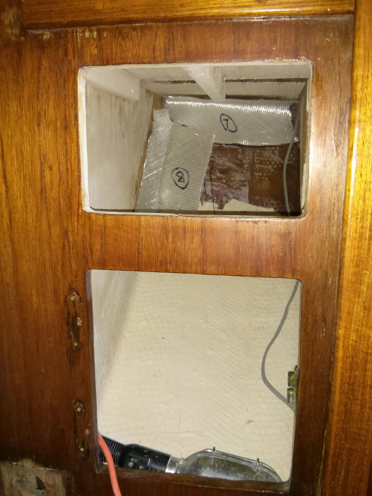
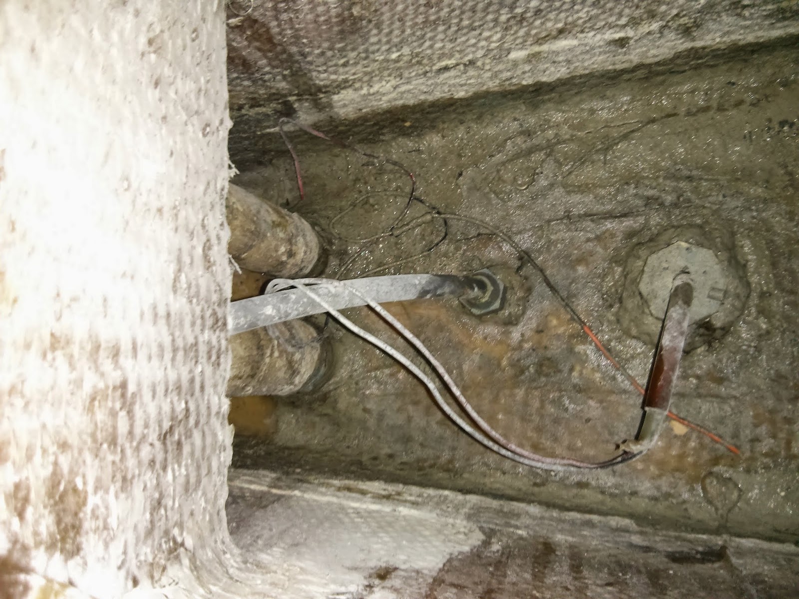
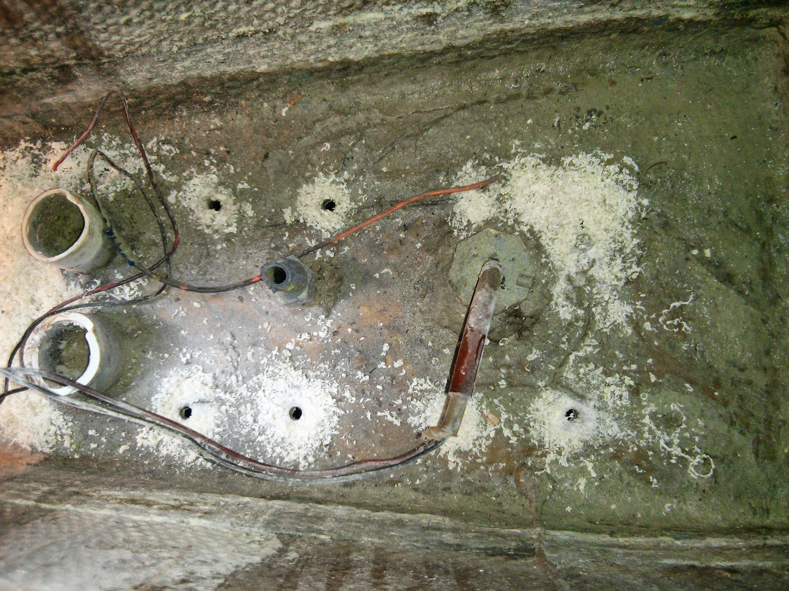
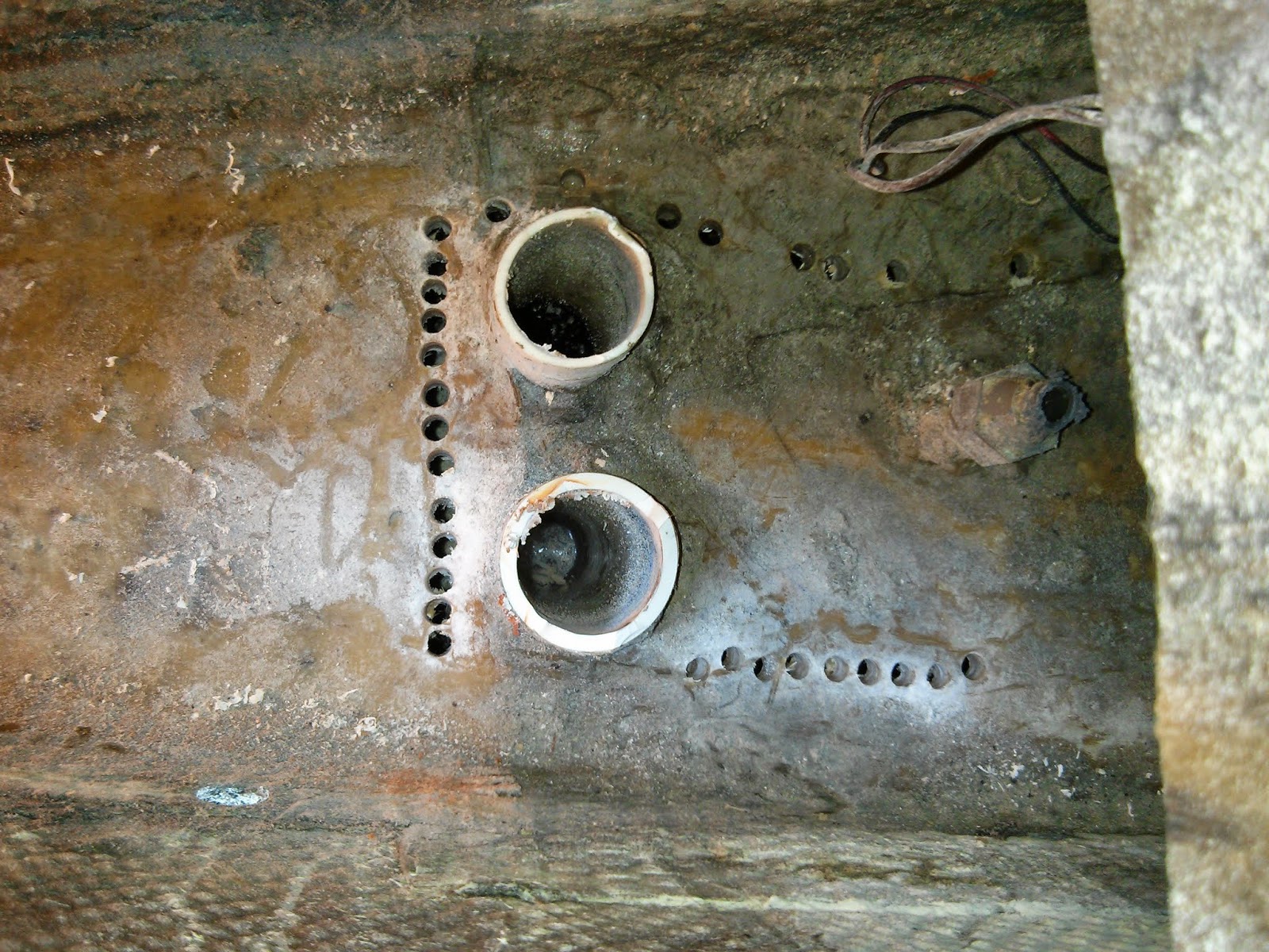
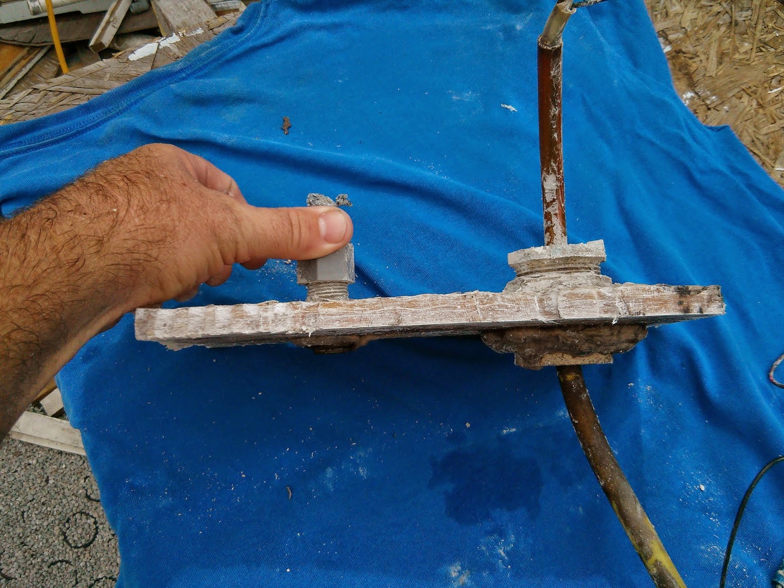
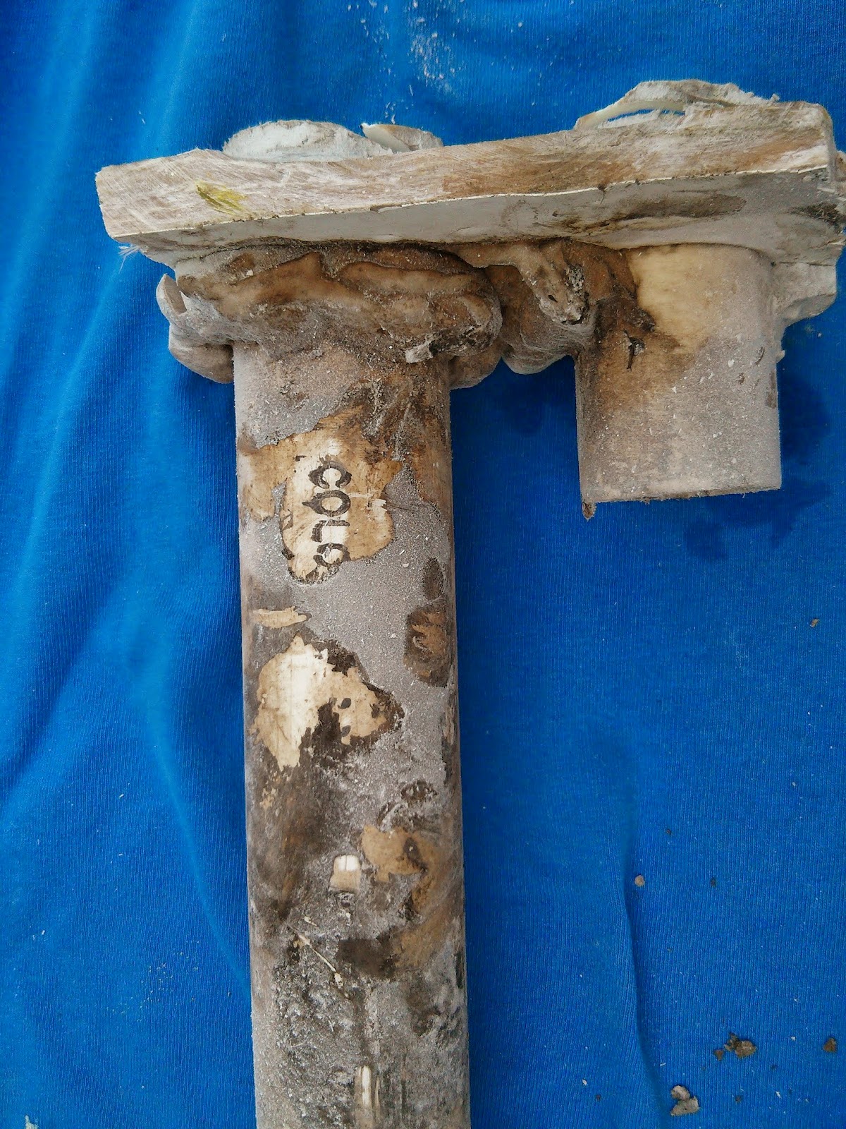
Opening these areas up will expose the aft lower chainplate hardware.  My preference is to have these critical components visible rather than tucked away behind a headliner.

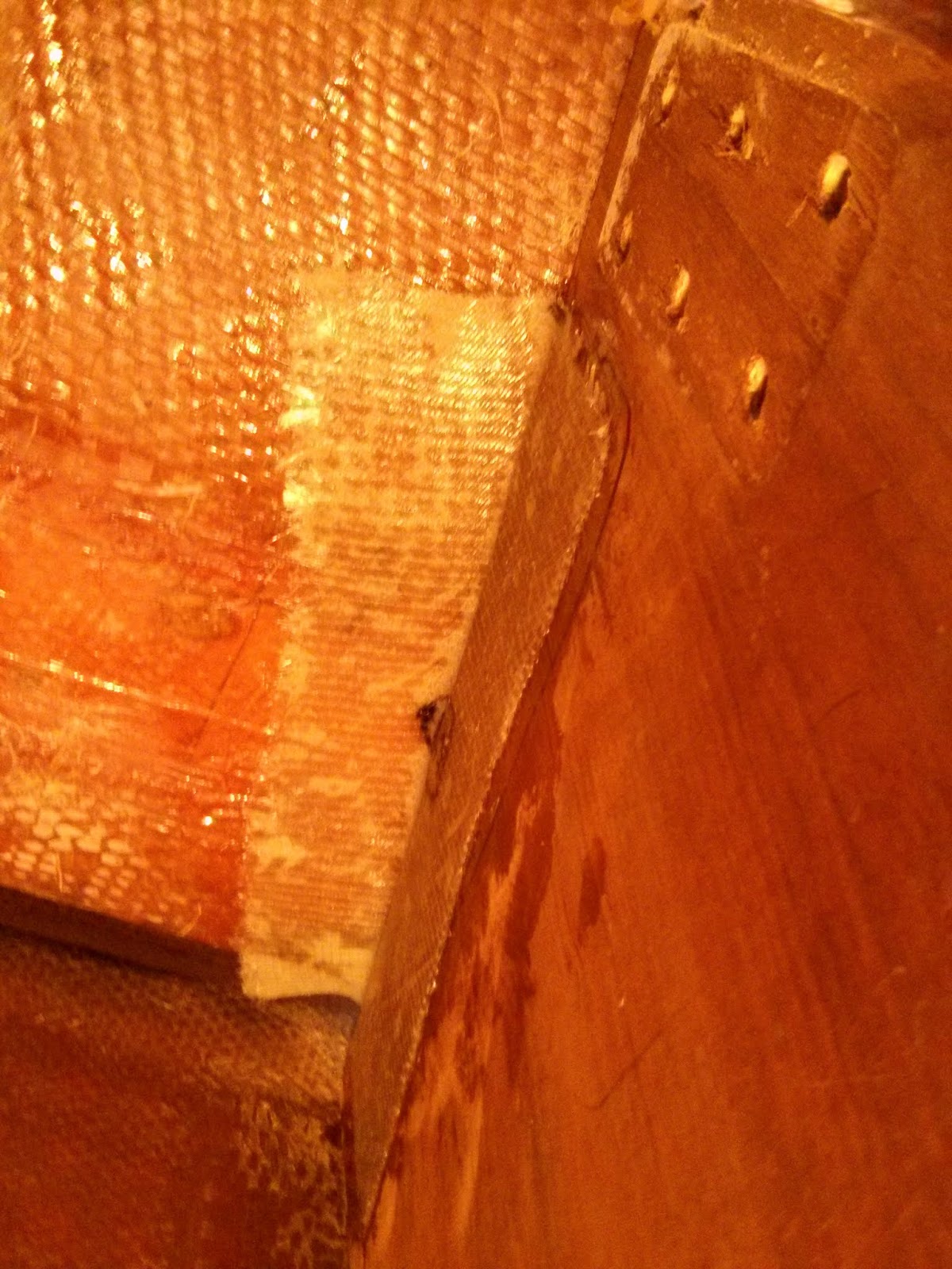
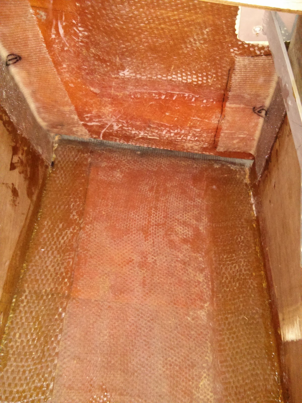
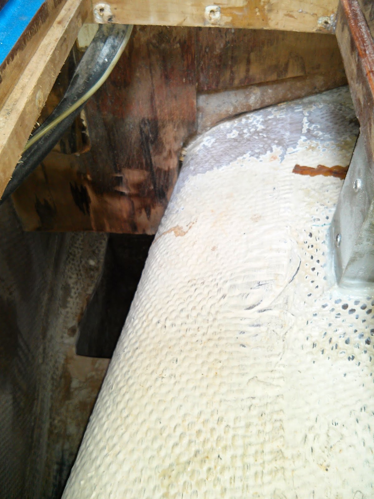
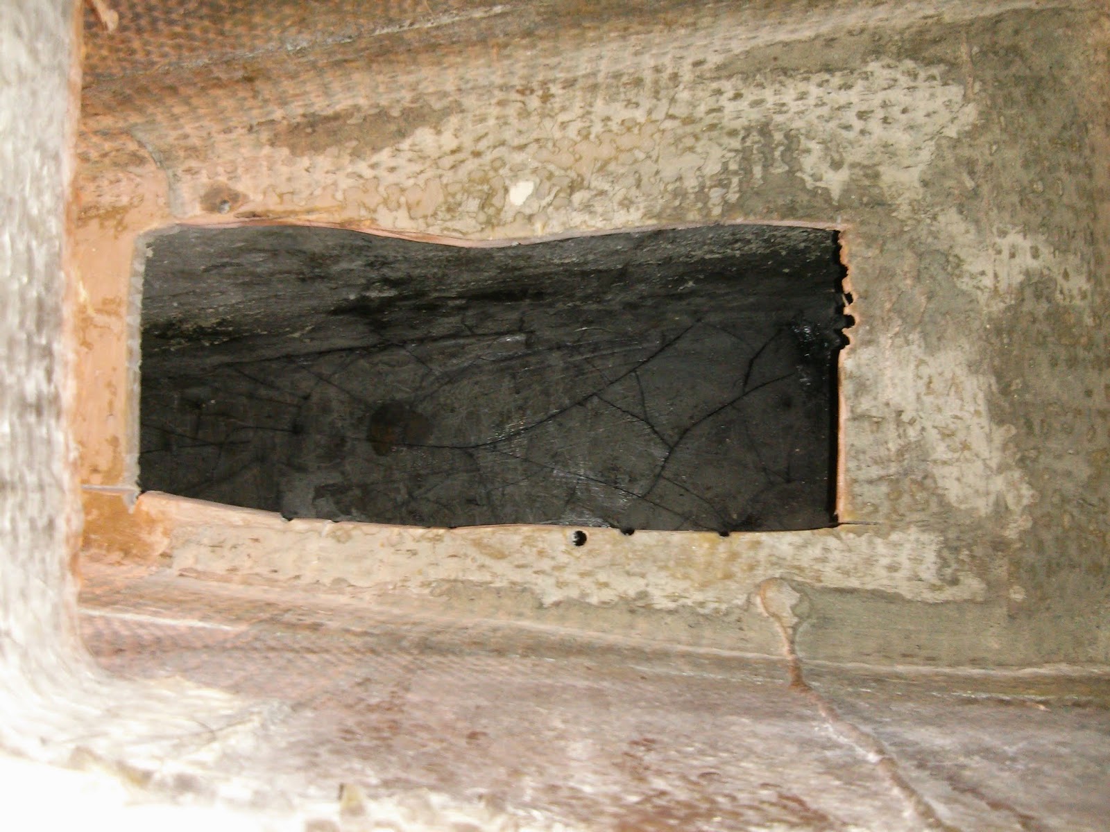
The underside of the deck was never intended to be visible so Morgan Yachts did not put any effort into cosmetically finishing the surface.  A few fiberglass burs and layer 
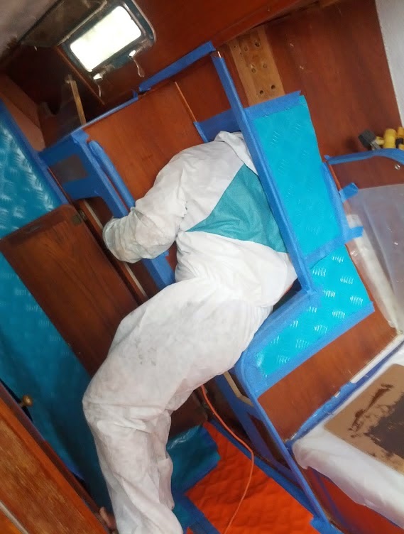
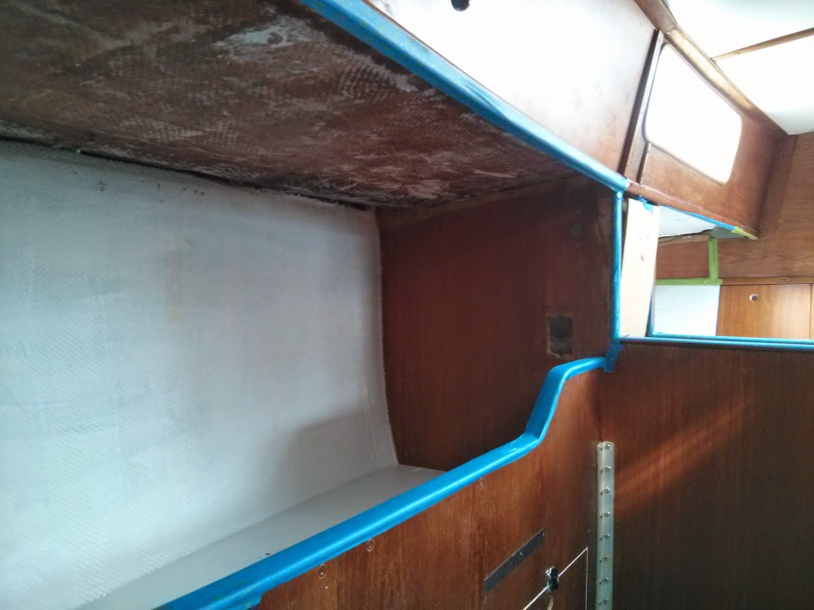
of chopped strand mat fuzz covered the surface.  Thus the project began with a particularly nasty round of grinding and sanding the underside of the deck above the original pilot berth on the starboard side of the salon.
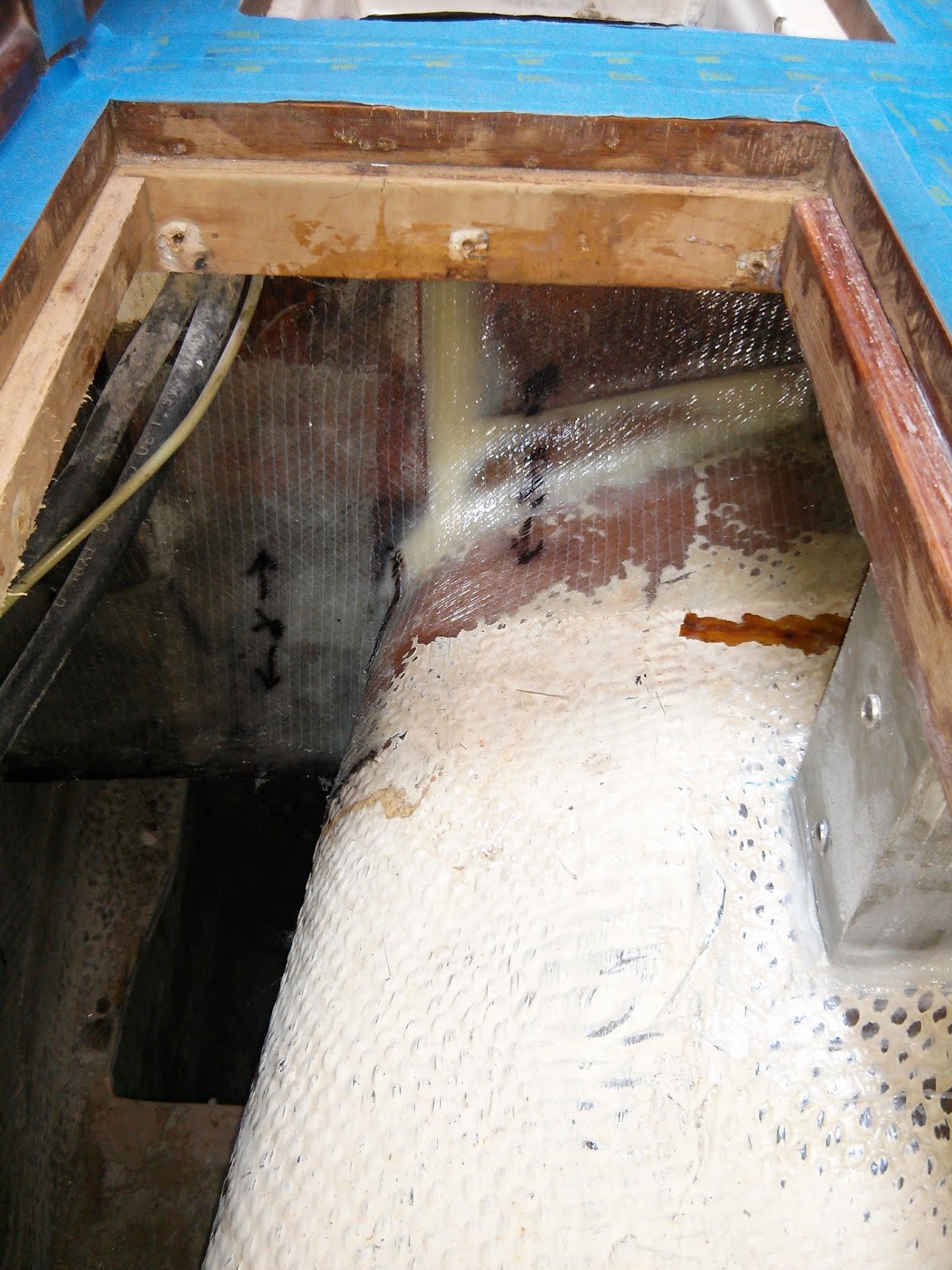
Underside of starboard side deck (above original pilot berth) after grinding down burs and sanded the entire surface with 80 grit paper.

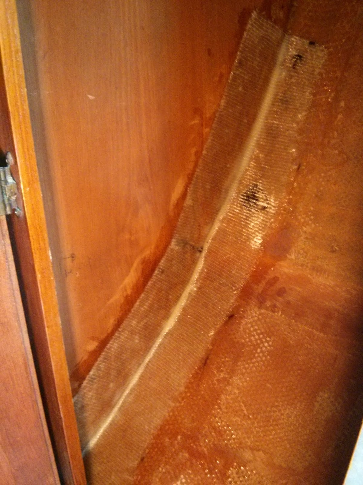
In an effort to corral the dust I draped a sheet of plastic sheeting down from the side wall above.  The post sanding accumulation of dust, dirt, and fiberglass fuzz was impressive.
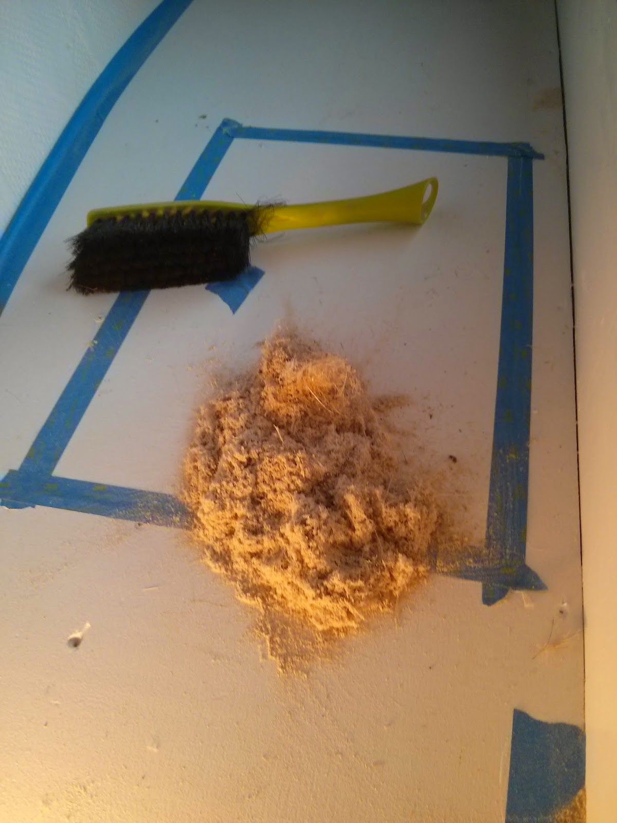
Accumulation of nastiness swept up after sanding overhead in pilot berth.

Cleaning the area post sanding required multiple passes with the shop vac and a couple wipe downs with denatured alcohol.  Once satisfied the area was clean, I taped it off for painting.
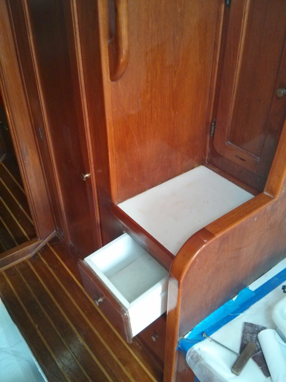
Look aft at pilot berth with nav station in background.
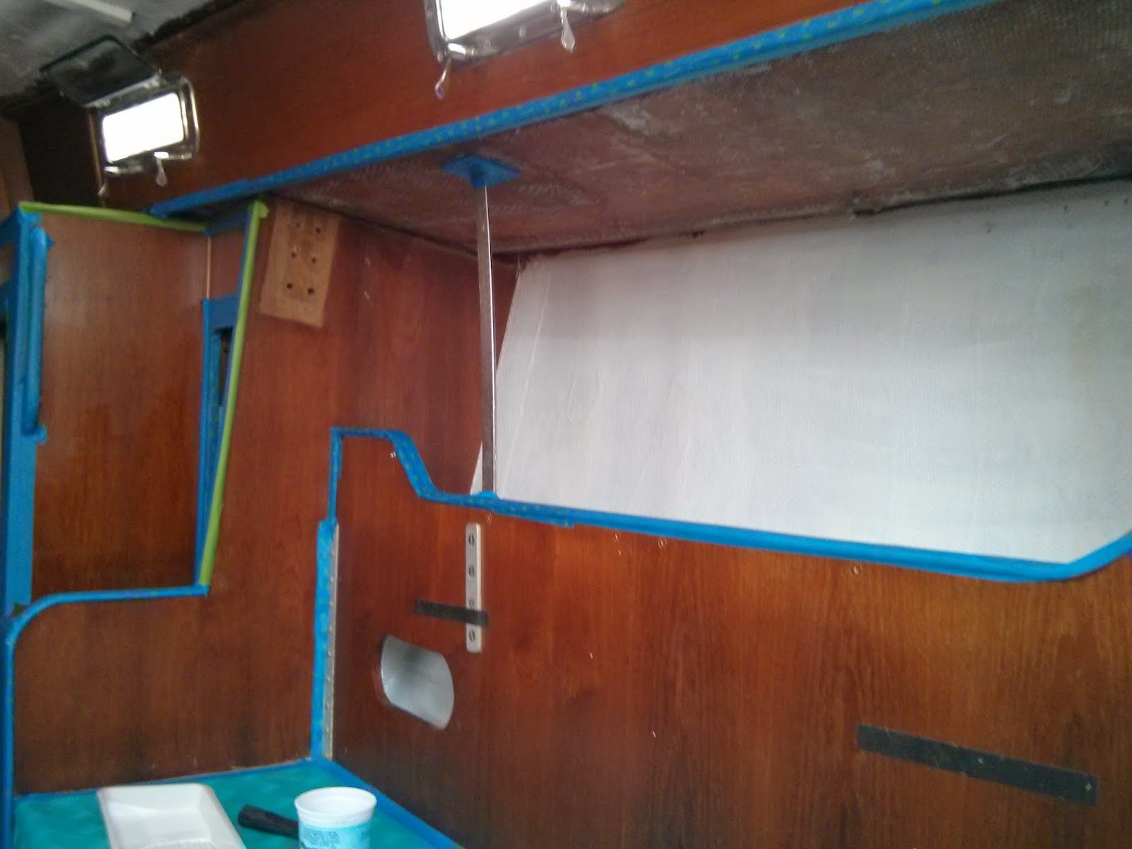
Looking forward at pilot berth and bulkhead to be painted.  Note cap shroud chainplate is removed.

Over a two day window the pilot berth overhead, the nav station overhead, the starboard bulkhead, and the interior of the starboard forward lockers received two coats of primer and two top coats of paint.
Looking forward at freshly painted bulkhead and pilot berth overhead.
Looking aft at freshly painted bulkhead and pilot berth overhead.

We plan to install fixed shelving in the original pilot berth area.  These modifications will also include some trim work to dress up the joints between the bulkheads and the overhead.  Images from the pilot berth modifications can be found in our Pilot Berth Rebuild Photo Album.
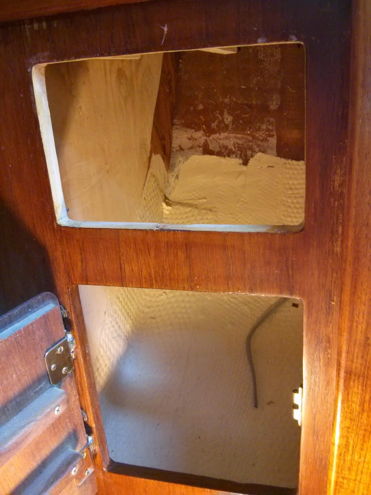
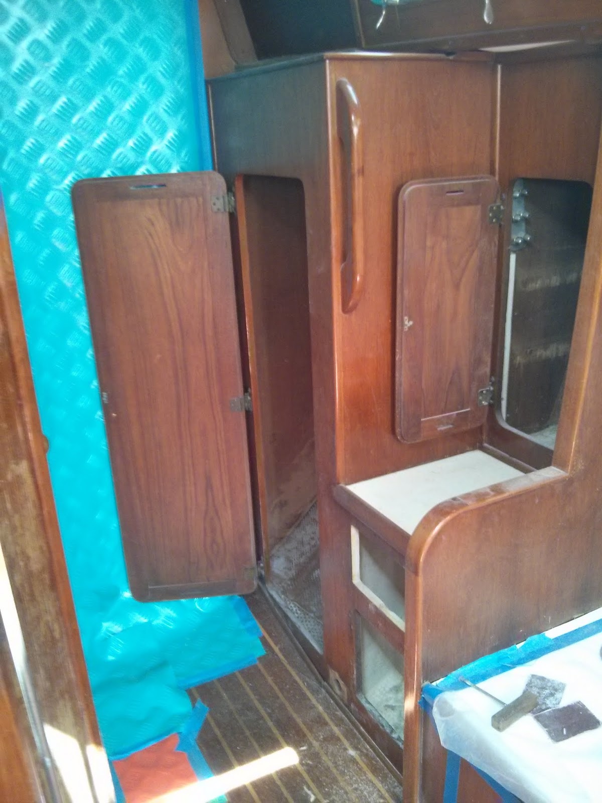
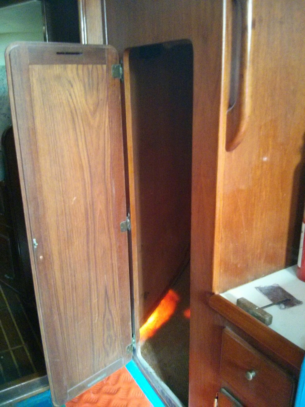
Freshly painted interior of starboard forward lockers.

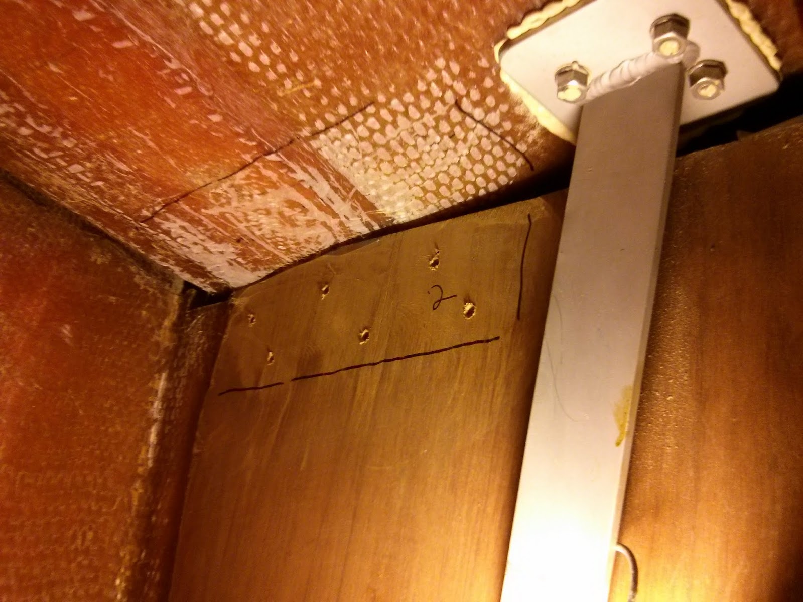
With the tabbing repairs complete and a fresh paint on interior of the starboard forward lockers, the next step on this front is to refinish and re-install the shelves and hanging rods.  Images of the tabbing repairs and modifications to this area can be found in our Starboard Forward Lockers Photo Album.
Freshly painted overhead and aft panel at nav station

Next up for the Nav Station will be the installation of the frame for the electrical panel and instruments.  Images of our modifications to this area can be found in our Nav Station Refit Photo Album.

We are pleased with the outcome and plan to continue the process on the port side once we re-install / re-bed the starboard chainplates and remove those on the port side.

In the next post I plan to share our discoveries and images from removing the chainplates.

Wednesday, August 20, 2014

Adding Tabbing to Starboard, Midship Bulkheads – Part 2

Here is a link to Part One -  Adding Tabbing to Starboard, Midship Bulkheads

Next step - cutting and test fitting sections of 1708 cloth. 
test fitting a 36" section of 1708 cloth along the lower section of the bulkhead dividing the salon and forward cabin.

The longest section requiring tabbing, the lower section of the bulkhead separating the salon and forward cabin, was directly above the greatest concentration of hairline cracks on the exterior of the hull.

The next bulkhead aft required less than a foot of new tabbing at its base on the forward side.  The aft side of the same bulkhead required around 14” of tabbing in a site previously hidden by a drawer.

Test fitting cloth in lower lockers forward of starboard salon seat / berth.
I elected to also add a section of horizontal tabbing between the hull and the ½” plywood shelf.

Since two of the three bulkheads in our current work zone serve as anchor points for chainplates, we have elected to add tabbing between these bulkheads and the deck.
Bulkhead / Deck joint just outboard of forward, lower chainplate prepped for tabbing.
In the image above, the bulkhead / deck joint prepped for tabbing is just outboard of the forward, lower chainplate.   Also visible in the image above is a series of countersunk #8 screws.  The interior of the larger lockers have ¼” plywood facade covering the ¾” structural bulkhead.  The original tabbing is either installed directly to the structural bulkhead under the façade or the 6” of the façade closest the hull  is cut away.  I contemplated removing the façade, but elected to leave it in place.  My guess is the ¼” plywood is bonded to the structural bulkhead with contact cement.  To strengthen the layup I added a series of #8 wood screws anywhere tabbing was to be applied atop the ¼” plywood.

Anne mixed epoxy and wet out the cloth while I applied the new tabbing.
The day the locker attacked Jeff.
The smaller lockers proved quite awkward to access while handling a sticky strip of fiberglass cloth.
new tabbing installed along bulkhead / deck joint just outboard of upper & cap shroud chainplate. The chainplate mounts in series of 6 holes visible in upper right of image.  
We added tabbing along all the bulkhead / deck joints in the lockers.
new bulkhead / deck joint tabbing in large hanging locker opposite head.
Also in short sections along both sides of the middle bulkhead that bears the load from the lower, forward chainplate.
new tabbing in area previously hidden by drawer.
 And one 36” strip along the lower section of the bulkhead dividing the salon and forward cabin.
New tabbing along lower section of bulkhead dividing salon and forward cabin.

Next step for this area is to prime and paint the inside of the lockers.

When we clear the cushions out of the forward cabin then bulkheads / lockers in that area will undergo a similar treatment. 

We will continue to add images from this project to our  Starboard Forward Lockers Photo Album.

Images and notes from all tabbing related repairs can be found in our Tabbing Repairs Photo Album.


Tuesday, August 19, 2014

Adding Tabbing to Starboard, Midship Bulkheads – Part 1

We foolishly though the tabbing repairs were complete. ..

The starboard lockers extending from the forward of the pilot berth in the salon to just aft of the vee berth in the forward cabin are constructed around a series of four bulkheads.   Like bulkheads in the head and galley we discovered that during construction Morgan Yachts intermittently tabbed the bulkheads to the hull.    Our mission for this project… fill in the missing sections of tabbing.

Simply exposing the hull in these lockers proved time consuming.    First all the shelving, hanging rods, and drawer hardware was removed.
Drawer just forward of starboard salon seat / berth.
We are not fond of drawers on the boat.  Often a great deal of space is devoted to the mechanics of the drawer.    As expected removing the slides and backstop of the drawer forward of the starboard salon seat revealed additional space outboard.  Sadly it also revealed an un-tabbed section of the bulkhead on the forward side of the drawer.
Removing the drawer backstop revealed additional space and a section of the bulkhead lacking tabbing, upper left.

This bulkhead serves as an anchor point for the forward lower chain plate.  Awkward as it may be we will be adding tabbing to this site.

In most of the lockers the hull was lined with a white, textured vinyl covering that seemed to serve as agar for growing mold.  With the shelving removed the vinyl covering peeled easily away from the hull leaving behind a gooey residue of aged contact cement.  MEK (methyl-ethyl-ketone) is the go to chemical for removing old contact cement.  MEK is toxic so personal protection equipment (PPE) is required.  When using MEK I don rubber, dishwashing style  gloves.  When using MEK in an enclosed space I wear a full face respirator with an organic vapor filter.   Once suited up it required a couple sweaty  hours of scrubbing the hull sections inside the lockers to remove all the old contact cement.  

To ensure any residual oil, dirt, grime, etc. would not compromise the bonding of future epoxy and paint, the next step was to wash down the interior of the lockers with TSP (tri sodium phosphate).  TSP is a heavy duty soap that we use prior to almost all interior painting projects.
Large hanging locker opposite head with liner removed and fiberglass cleaned.  This section above the waterline is tabbed to the hull along both sides. Note forward lower chain plate at top right of image.
With the fiberglass hull exposed and clean the next step is to lightly grind the areas that require tabbing.  The grinding serves to remove any irregular bumps or burs while also creating a rough surface to which the epoxy can adhere.  This step generates noxious dust.   Since the vee berth is currently providing clean storage for all Pilgrim’s cushions we sealed off the forward cabin and focused our efforts on the lockers / bulkheads opposite the head at the forward end of the salon.
Dust from grinding litters the sole outside the lockers.  Vee berth is masked off to protect cushions.


To be continued…

Saturday, August 16, 2014

They Just Do Not Make Them Like They Used To...

Each time we shed fresh light in a dark recess or remove a cosmetic facade to reveal Pilgrim’s structural underpinnings, I find  myself muttering the clichéd line, “They just don’t make them like the used to.” They would be Morgan Yachts and them is sailboats.  

My comparison is between our 1966 Morgan 34
C'est la Vie - 1966 Morgan 34 
and our 1979 Morgan 382.
Pilgrim - 1979 Morgan 382, Hull #115
Now I’m sure the heart rate and blood pressure of some Morgan 382 owners and admirers out there is on the rise, but hear me out. 

I do not feel that the Morgan 382 series is poorly designed.  I am aware that most of the 382's commissioned are still on the water and include hulls that have crossed oceans and circumnavigated the globe. I remain very eager to get Pilgrim back to the water, cast off the dock lines, and point her bow towards the horizon. 

BUT…  It is obvious to me that during the construction of the M382s corners were cut.  My best guess is that the issue lies at the intersection of three factors.
  1. Apathy on behalf of hourly workers cranking out 50?, 100?,  or more?  vessels each year.
  2. Pressure on the construction team to speed up production to meet market demand.
  3. Efforts to maximize profits by keeping fabrication costs in check.

Ok, thus far my rant is simply opinion and conjecture.  Allow me to share our latest discoveries on Pilgrim…

ONE...
Working in the bilge, I noted that the cross brace under the sole that links the partial bulkhead forward of the galley countertop on port with the partial bulkhead  just forward of the nav station on starboard was only tabbed to the hull on the forward side.  
Cross brace under cabin sole lacks tabbing on aft side.
Feeling the tabbing was inadequate, I added a couple layers of 1708 cloth tabbing to the aft side of the brace.
Tet fitting 1708 cloth sections along cross brace.
Tabbing installed along aft side of cross brace.
That evening I reviewed an image of the original construction plans for the bilge.

Original construction plans call for tabbing on both sides of cross brace.
In the original plans the brace is tabbed on both sides.

TWO...
Early this week while removing bottom paint along the starboard forward hull, I discovered vertical cracks in the gel coat.  Grinding the area out revealed damage that closely resembled that on the port side where the head pan settled directly on the hull.
Upper right area is remarkably similar to damage discovered under the head pan on opposite side of hull.
After grinding out the area, I went inside to investigate and discovered the cracks are directly under an un-tabbed section of  bulkhead. 
Glowing area below bulkhead in closet reveals location of damage on hull exterior.
Direct pressure from the un-tabbed, lower section of the bulkhead is the cause of the cracks and subsequent water intrusion.
Woven-roven tabbing along the bulkhead stops few inches above the waterline. 
The tabbing along the aft side of the bulkhead stops just above the waterline.

Forward side of bulkhead lacks tabbing along it's entire length.
The forward side of the bulkhead lacks tabbing along its entire length.  Minimally internal bulkheads should be tabbed on one side wherever they make direct contact with the hull.   Ideally the bulkheads are tabbed for their full length on both sides.   

All the bulkheads in our 1966 Morgan were tabbed on both sides along their entire length.  When Pilgrim returns to the water her bulkheads will also be tabbed along their entire length. 


I’m headed back to the boat to soldier on while muttering, “They just don’t make them like they used to.”

Thursday, August 14, 2014

The reality of Pilgrim's Head Plumbing

Note:  To preserve the narrative of Pilgrim's refit this post and diagrams will remain available to readers.  There are design flaws in the plumbing diagrams depicted on this post.  If you are seeking black water diagrams for use on another vessel, then please see our September 30, 2014 post - Holding Tank and Blackwater Plumbing Complete.  Thanks.

Thanks for all your comments and questions on my plumbing schematic for Pilgrim's head.
In the ideal world of plumbing schematics.

Sketching out the system in the 2D world of Google Drawings and actually making the plumbing fit into the space available while conforming to the laws of physics are two very different animals.

I've collected all the components and begun to experiment with the actual installation.  Below is a more accurate image of the routing of plumbing for Pilgrim's head...
The reality of Pilgrim's head plumbing.
With the exception of two changes to hardware, the system above functions identically to the schematic in the original plan.

Comments both on our website, and on the M38 Owners Board inspired me to revisit the possibility of employing the Whale MKV Maunal Pump rather than a Shurflo electric macterator pump.  The Whale MKV pump was part of the Lavac head system on C'est la Vie.  In the 9 years we traveled aboard the pump proved reliable yet simple and relatively easy to service. We already own both the pump and a rebuild kit.

Mounting the pump under the head counter top on the centerline wall works well.  The socket for the removable pump handle will be accessible from the hall outside the head.  This location is eclipsed by the mast when viewed from the salon / galley so I do not believe it will present an eyesore.  If necessary I will fabricate a cover for the handle socket.  This installation places all the pump fittings and the clean out port in easily accessible locations that are also above the waterline.  The drawing above places the pump below the level of the tank discharge.  I plan to install the pump so that it is level with or slightly above the level of the "Y' valve at the exit of the tank.

The second hardware modification is the removal of the 1 1/2" valve at the exit of the tank.  Plumbing the shut off valve between the tank and the "Y" valve splitting the pumpout and the offshore discharge took up a great deal of space.  I believe the "Y" valve will provide enough control to facilitate repairs while mitigating messes. This is the method we used successfully aboard C'est la Vie.

Hopefully this post marks the end of posting plumbing drawings and I will have some images of the installation soon.

Monday, August 4, 2014

To "Y" Valve or "T" Junction - That is the Question.

Note:  To preserve the narrative of Pilgrim's refit this post and diagrams will remain available to readers.  There are design flaws in the plumbing diagrams depicted on this post.  If you are seeking black water diagrams for use on another vessel, then please see our September 30, 2014 post - Holding Tank and Blackwater Plumbing Complete.  Thanks.

The most consistent critical feedback regarding my proposed head plumbing diagram is use of a "Y" valve just downstream of the holding tank.  In the diagram below I have labeled the "Y" valves 1, 2, & 3.
Valve #3 is the one in question.  It directs waste to either the deck pump out or the macerator. Multiple people have suggested using a "T" junction rather than a valve.  Below is a plumbing diagram with the "T" joint rather than "Y" valve #3.

My personal debate lead me to the following pros & cons of each set up

  • The total number of joints & hose clamps  (a.k.a possible failure/leak points) in the system is the same in either set up.  
  • The "T" joint costs significantly less than a "Y" valve.  But - we already own both a "T" joint and a "Y" valve so the cost for us is not a consideration.
  • The "T" joint will allow for a bit more waste storage since the volume of the hose is always open to the holding tank.
  • The "T" joint has no moving parts and thus is less prone to failure.
  • In the event of repairs or clogs downstream of the holding tank the "Y" valve would allow for greater control of waste and likely result in less direct contact with waste while making repairs.
  • In Pilgrim the 90 degree joints on the  "T" make the hose runs a bit neater than the 120 degree joints on the Forespar "Y" valves.
The lingering question I was unable to answer personally was... Is it detrimental to the macerator to have a strong vacuum pulled on it during a pump out.  I took this question to the owners of Burbridge & Wilson Marine Refit, Restoration, and Repairs part of the Jarrett Bay Marine Complex.  They recommend that "Y" valve be used as pulling a vacuum on macerator pump could damage the seals. Additional they noted that the "Y" valve also reduced the number of joints (possible sources of leaks) subject to negative vacuum pressure during a pump out.  They did cite a significant cost difference as a reason to consider using the "T" joint.

As a side note we have received comments from two people that recommend passing all the waste through the holding tank as a method of simplifying the system.  

Channeling all the waste through the holding tank greatly simplifies the plumbing. This design reduces the cost and number of possible points of failure.  I feel this is a good option for vessels operating in areas where pump out facilities are readily available.   When traveling in areas with few pump out facilities (i.e. Bahamas, Caribbean, Mexico, Central America, etc.) then a such a system is wholly reliant upon the macerator pump.  If the macerator pump fails or clogs and no pump out facility is at hand then the head is non functional until repairs are made.  I would feel more at ease traveling with this system if a manual pump (e.g. Henderson MKV) replaced the electric macerator.  Available space and access under the head counter on Pilgrim really does not allow the option of the manual pump. 

Thus we are inching towards installing the original design with three, yup three, "Y" valves.

Thanks to everyone that has contributed to this conversation both here on the website, on Google+, and over at the Morgan 38 Message Board.

Sunday, August 3, 2014

Head Plumbing Diagram - Follow Up Post

Note:  To preserve the narrative of Pilgrim's refit this post and diagrams will remain available to readers.  There are design flaws in the plumbing diagrams depicted on this post.  If you are seeking black water diagrams for use on another vessel, then please see our September 30, 2014 post - Holding Tank and Blackwater Plumbing Complete.  Thanks.

Thanks for all the follow up comments and questions about my proposed head plumbing for Pilgrim.  I am not a marine plumbing expert.  Additional perspectives provide me with the opportunity to assess my proposed system prior to committing time and resources to the installation.


A couple details to note in the original diagram (above)...
To comply the laws that require the valve permitting waste to be discharged from the vessel directly into the water, I will need to place a lock on either the thru-hull fitting or on the two "Y" valves closest to the holding tank.  My preference would be a single lock on the thru-hull.

The valves depicted in the diagram are Forespar "Y" valves. We are re-using valves removed from C'est la Vie.

To clarify my intentions I created a few new diagrams that illustrate the flow of waste through the system in various situations.

When set up to flush the head directly overboard the waste will follow the path highlighted in red below...

When set up to flush into the holding tank waste will follow the path highlighted in red below...
When set up to empty the holding tank via a pump out facility the waste will follow the path highlighted in red below...
When emptying the holding tank offshore via the macerator pump the waste will follow the path highlighted in red below...

I hope the additional diagrams assist in illustrating my intentions.  Please keep posting questions and comments.

Bilge Modifications - Part 1

As I discussed in the Installing A Holding Tank In The Head post,  the original Morgan 382 design placed the holding tank below the bilge in the aft lower section of the keel.  Below is a blueprint of the area from the original plans –
Blueprint of the aft lower keel on a Morgan 382.
Pilgrim developed a leak between the floor of the bilge and the holding tank area.  I learned from the Morgan 38 Message Board, that other M382 owners have dealt with similar issues.   

My best guess is that the bilge floor leaks around the plumbing fittings.
Floor of bilge is perforated by plumbing for the holding tank. From aft (left) to fore (right) - PVC pipes serve as inlet and outlet for waste, grey tubing is holding tank vent, and plug with wires is sensor that indicates tank is over 3/4 full.
The new holding tank installed in the head eliminates the need for an inaccessible void in the lower keel.  I prefer to have access to the area to permit visual inspections and allow Pilgrim’s bilge pumps to properly eliminate all standing water inside the vessel.

I began by drilling 3/8” holes to serve as an outline the area to be removed.
Drilling 3/8" holes to mark the perimeter of the section to be removed.
While drilling the holes, I realized that creating a series of drilled holes would generate less fiberglass dust than other either using a jigsaw or a grinder with a cut off wheel. 
Series of holes complete.
The excavation did ultimately require a combination of drilling, jigsaw, and finally grinder with cut off wheel…

Working with power tools in the confined space with limited access required patience.
Eventually the fiberglass bilge floor succumb to my efforts.  I will spare you the image of fiberglass dust floating atop the black water below and the details of using a shop vac & scouring pads to clean the area.  If you want all the images check out our Bilge Modifications Photo Album.
I was not expecting the floor to be a consistent 1/2" thick.
 The consistent 1/2”+ thickness of the bilge floor surprised me.  The thickness of the material leads me to believe that it serves as a structural member of the aft section of the keel.   Good thing I only removed a small section from the center of the floor.

The source of the leak never revealed itself.  I’m still betting the leak existed around the PVC pipes that served as the inlet and outlet for the waste.
I believe the PVC pipes were the source of the leak(s)
Pilgrim now has an upper and lower bilge area.

The upper and lower bilges are now clean and dry.
Our plan is to allow a few weeks for the lower section to completely dry out.  We will then apply barrier coat, paint, and finally install bilge pumps & float switches.

Saturday, August 2, 2014

Head Plumbing Diagram

With non-stop rain here in eastern North Carolina, I've had plenty of time to sketch out a proposed plumbing diagram for the head.

Questions, comments, or concerns are welcome.